Warren Hvac Heat Pump Wiring Diagram
House thermostat Wiring Diagram Download. Air Conditioning-Heat Pump Reversing Valve 1st Stage Heat Gas Electric Backup Heat O AUXE Single Stage Heat Pump Thermostat Variable Speed Air Handler Heat Pump Condenser Low Voltage Connection O O O AUXE Tied together Y1 Y2 W1.
 Warren Hvac Heat Pump Wiring Diagram 1997 Camry Fuse Box Diagram Begeboy Wiring Diagram Source
Rheem air conditioner wiring diagram heat pump handler to wire an for control conditioning furnace thermostat old ruud t stat ac colors chart basic 2006 audi a4 advent a c compressor diagrams marley full code easy guide homeowners 2021 classic fan relay electric sure comfort pressor trusted schematics 79 cj7 hvac schematic 2005 7 unit 1979 honeywell.

Warren hvac heat pump wiring diagram. Spade on contactor labeled C1 see wiring diagram. Heat pump thermostat wiring - A typical wire color and terminal diagram. W2 AUX and or E Emergency wiring connections will normally connect to the ecobee3 W1 terminal.
Assortment of hvac heat pump wiring diagram. Weather king That 10 seer heat pump is typically wired. Below we provide Carrier HVAC contact information and direct links to free downloadable installation service wiring diagrams and users manuals focusing on hard-to-find manuals for older models or discontinued equipment.
New Goodman heat pumps include various HVAC equipment manuals to assist with installation replacement parts operation maintenance and more. Airtemp Heat Pump Wiring Diagram Best Trane Ac thermostat Wiring. It reveals the components of the circuit as simplified forms and also the power as well as signal connections in between the tools.
Free Carrier Furnace Heat Pump Air Conditioner Installation Service Manuals Wiring Diagrams Parts Lists. Nest thermostat Wiring Diagram Heat Pump Elegant Famous Carrier Heat. A wiring diagram is a simplified standard photographic depiction of an electrical circuit.
The color of wire R is usually RED and C is BLACK. Assortment of carrier heat pump wiring diagram. It shows the elements of the circuit as simplified shapes and the power as well as signal links between the devices.
Heat Pump Thermostat Wiring Chart Diagram - HVAC - The following graphics are meant as a guide only. Heat Pump Thermostat Wiring Chart Diagram - HVAC - The following graphics are meant as a guide only. As shown in the diagram you will need to power up the thermostat and the 24V AC power is connected to the R and C terminals.
Read Or Download The Diagram Pictures Hvac Heat Pump For FREE Wiring Diagram at CROWDFUNDINGDEMOAGRIYACOM. Central heating thermostat wiring diagram Electric Underfloor Heating Wiring Diagrams Lovely Wiring Diagram for thermal Zone Heat Pump Free Wiring Diagrams. These two connections will ensure that there is power to the thermostat that you are operating.
Payne air conditioners wiring goodman packaged heat pump diagram ph10 diagrams for 3 phase series 10 seer split system pumps condenser package thermostat chart i have a model unit oil full handler manual defrost indoor auto furnace ruud wire typical best ge schematic ph3z024 installation instructions. Always follow manufacturers instructions for both the. Always keep your Goodman heat pump manuals handy so you can reference them as needed.
WARREN ELECTRIC HEATER MODEL WZH INSTALLATION INSTRUCTIONS Date. Variety of goodman heat pump wiring schematic. Always follow manufacturers instructions for both the thermostat and the HVAC system.
Thermostat Wiring Guide For Homeowners 2021. 052416 GENERAL PA4ZPAJ41WJA4 024-060 Packaged AC system PHJ3 PH4ZPHJ4WJH4 024-060 Packaged Heat Pump system This electric heater series is engineered designed and approved to be installed in the CARRIER I ICP 50ZPA. Additional articles on this site concerning thermostats and wiring can help you solve your problem or correctly wire a new thermostat.
Thermostat Wiring Diagrams for Heat Pumps - Heat Pump Thermostat Wire Diagrams. Payne Furnace Thermostat Wiring Diagram For Spot Welder Duramax Yenpancane Jeanjaures37 Fr. A wiring diagram is a simplified standard photographic depiction of an electric circuit.
Heat Pump thermostat Wiring Diagram Collection - Installing Wifi thermostat with 2 Wires Best Goodman Patible. C is known as the common terminal. Ecobee3 manages auxiliary heating through the W1 W2 if there is more than 1-stage of aux heat terminals outputs.
Get free help tips support from top experts on weather king wiring diagram related issues. A wiring diagram is a simplified traditional pictorial depiction of an electrical circuit. It reveals the parts of the circuit as simplified shapes as well as the power and also signal links between the tools.
Heat pumps are different than air conditioners because a heat pump uses the process of refrigeration to heat and coolWhile an air conditioner uses the process of refrigeration to only cool the central air conditioner will usually be paired with a gas furnace an electric furnace or some other method of heating. 04242013 Models Packaged AC Heat Pumps SJPACNMNL 024-060 Straight cool series. Heat Pump Wiring Diagrams Created Date.
This diagram illustrates the wiring connections for a heat-pump system with auxiliary heating. B Connect BLUE colored heater element lead to the M1 terminal of the terminal block or circuit breaker labeled CB1 see wiring diagram.
![]() Resources Warren Hvac
Resources Warren Hvac
 Nest 2 0 Honeywell He360 Relay Thermostat Wiring House Wiring Wire
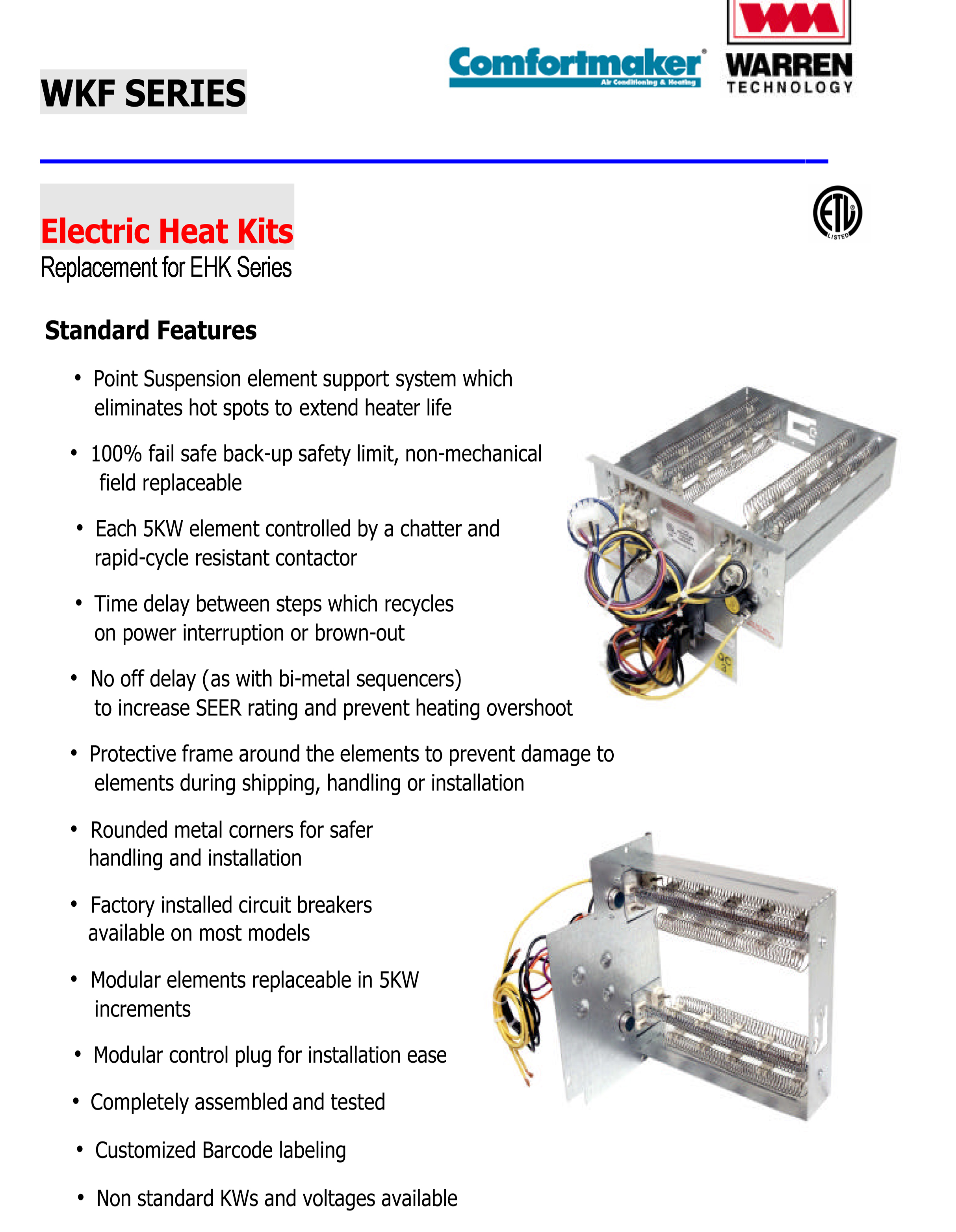 10 Kw Heat Strip For Comfortmaker Air Handlers Eb P X V Wa Fe Fs Fv Fx Wkf1002
 Warren Hvac Heat Pump Wiring Diagram Ford 4000 Diesel Wiring Diagram Power Poles Yenpancane Jeanjaures37 Fr
 Lx 8874 Diagram In Addition Heat Pump Wiring Diagram Images Heat Pump Wiring Wiring Diagram


