Audio Xlr Wiring Diagram Meaning
The above diagram shows you the pin numbering for both Male and Female XLR connectors from the front and the rear view. XLR to inch stereo jack plug.
A 3 way swap has two terminals that are both silver or brass coloured and a person.
Audio xlr wiring diagram meaning. Electronic wiring majorcom diagram for xlr to 1 4 stereo unbalanced jack 3 5mm full 5 pin hd mono microphone output mini cable soldering schematics how thermo disc analog audio signal types explained 6 wire phono stareo trs seniorsclub 1998 ford 1995 240 bathroom cartoon 1024 720 transp male. How to wire an xlr two rca connectors. Xlr cable wiring diagram welcome to our site this is images about xlr cable wiring diagram posted by ella brouillard in xlr category on may 12 2019.
Pin 2 on the XLR is hot and carries the positive going signal whilst pin 3 is cold and provides the return. This pictorial diagram shows us a physical connection that is much easier to understand in an electrical circuit or system. A wiring diagram is a streamlined conventional photographic depiction of an electric circuit.
But theres one professional connector that is still soldered the venerable XLR. XLR3 cable connectors female on left and male on right The XLR connector is a type of electrical connector primarily found on professional audio video and stage lighting equipment. Collection of xlr to mono jack wiring diagram.
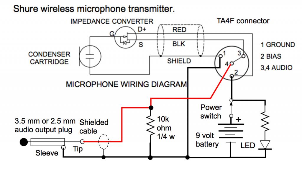
Xlr to rca cable wiring diagram. XLR pin 1 shield Amphenol pin 1 XLR pin 2 low impedance audio hot Amphenol pin 4 white wire typically XLR pin 3 low impedance audio return Amphenol pin 3 black wire typically Note. See wiring diagrams for compatibility with wireless brands.
Pin 2 on the XLR is hot and carries the positive going signal whilst pin 3 is cold and provides the return. As you see in the diagram below there are three male pins inside the connector. It is made by many manufacturers including Neutrik Switchcraft Amphenol and many others.
The groundwire the hot signal and the cold signal. If the signal source is equipped with a cross coupled output stage. In america electricians and electrical contractors are legally required to comply with the national electrical code nec for.
XLR XLR cables can send balanced audio signals up to 200 feet. Xlr Wiring Diagram Pdf is a visual representation of the components and cables associated with an electrical connection. Professional video connectors are crimped.
The rear view is the end you solder from Here are the connections on each pin. The usual way to connect a 3-pin XLR to a 14 TRS AKA stereo jack plug is to use the following pin allocation. Van den Hul Audio CableConnector Wiring Diagrams Female Balanced XLR TO Male Unbalanced RCA Fig.
XLR connectors have been the standard balanced connector in the professional audio market for decades. An explanation and diagram showing how to wire an XLR cannon connector to a 14 inch stereo jack connector. It has become the universal standard for audio wiring.
Wiring Diagram For Xlr To 1 4 Stereo Jack 7 Way Trailer Color Doorchime Kankubuktikan Jeanjaures37 Fr. 3 Pin XLR Wiring Standard 3 Pin XLR connectors are standard amongst line level and mic level audio applications. It reveals the components of the circuit as streamlined shapes and the power as well as signal links between the devices.
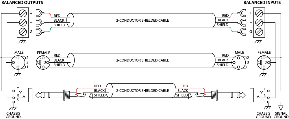
A balanced cable with a male XLR connection and one end and a female XLR at the other is often refered to as a mic cable because it is commonly used to connect microphones to mixers. See wiring diagrams for compatibility with wireless brands. The connectors are circular in design and have between three and seven pins.
This is the Sennheiser mini-to-male XLR audio output cable to be used That way I have a nice wire or wireless mic for. A balanced system is used in pro audio systems xlr wiring diagram shown below with an overall screen covering a twisted pair. Audio xlr wiring diagram meaning the distinction between a regular switch and a 3 way swap is one added terminalor link.
You will find that XLR connectors 3 pin pairs 4 pin and 5 pin are also a common choice for stereo balanced headphones. On the four pin Amphenol pin 2 is a high impedance unbalanced output. It shows the components of the circuit as simplified shapes and the capability and signal contacts amid the devices.
The audio signal is carried in anti-phase on the positive and negative wires and this is decoded at the receiving end to extract the audio signal. If the signal source is equipped with a pseudo balanced output stage. If the signal source is equipped with an output transformer.
Point Source Audio microphones are compatible with many popular wireless microphone systems. XLR to 14 TRS Connector wired for balanced mono. TRRRS connectors are used to support balanced stereo signal.
An unbalanced cable with a phone connector at each end is often refered to as a line cable. Xlr to Phono Wiring Diagram wiring diagram is a simplified agreeable pictorial representation of an electrical circuit.

 35 Mm Stereo Wiring Diagram Audio Studio Electronic Circuit Projects Trs
Sound System Interconnection
 Why You Need Balanced Not Unbalanced Cables For Studio Monitors Musicians Hq
 Diagram Xlr Speaker Wiring Diagram Full Version Hd Quality Wiring Diagram Diagramgwenl Megusta Ristorante It


