1991 Ford F 150 5 0 Wiring Diagram
Ford Alternator Wiring Diagram This is the diagram of every components in the alternator. Its components are shown by the pictorial to be easily identifiable.
It will take you to the Connector Face View page where there is a box that says Check.

1991 ford f 150 5 0 wiring diagram. Does anyone know where the ground locations are that feed. Ford Truck Diagrams and Schematics. Wiring diagram for 1991 ford f 150 center 91 f150 schematic more harness pcm radio filter ignition horn diagrams fuel gauge tail light 89 pump starter engine truck alternator 1987 lariat 92 f250 1998 stereo part 1 system circuit fuse box solenoid 1995 1994 04 chevy 2005 mazda.
Ford EFI injector wiring conversion Bank firing to Independently fired - Figure A 1990 50 HO EFI Mustang Wiring - Drawing A Ford 74 IDI Diesel Glo-plug controller by-bass wiringFigure A. Dec 28 2013 - My 93 F150 302 has an issue with a slightly rough idle a slight hesitation when pressing the gas and a surging when at a constant throttle position. Automotive Wiring Diagrams within 1991 Ford F150 Fuse Box Diagram image size 480 X 690 px and to view image details please click the image.
Here is a picture gallery about 1991 ford f150 fuse box diagram complete with the description of the image please find the image you need. 1986 ford f150 engine wiring diagram collection wiring diagram rh galericanna 1986 ford f250 wiring diagram Ford Motorhome Wiring Diagram 1991 ford f150 wiring diagram wiring diagram rh magnusrosen net Ford F 150 Starter Wiring We collect plenty of pictures about 1991 ford F150 Engine Diagram and finally we upload it on our website. It shows the components of the circuit as simplified forms and also the power and also signal links between the tools.
Nov 12 2016 1991 Ford F150. I have checked resistance from the PCM connector PCM unplugged to both a battery post ground as well as a body ground. There is less resistance from the connector to the battery post 9-11 ohms versus a body ground 20 ohms.
Particularly one that shows the wiring colors coming into the right fender mounted starter solenoid. Ford F150 1987 1991 fuse box diagram. Alternator Voltage Regulator Instrument Panel Starter and Drive Distributor.
Variety of ford f150 wiring diagram. Turns out someone had cut and spliced the wires incorrectly on the right side just before. Hey man hope you can help.
A wiring diagram is a simplified standard photographic representation of an electric circuit. 1987 1988 1989 1990 1991. 1991 Ford F 150 5 0 Wiring Diagram It is far more helpful as a reference guide if anyone wants to know about the homes electrical system.
It reveals the elements of the circuit as simplified shapes as well as the power and also signal links between the devices. Fuse box Ford F150 fuse box diagram. 2003 Ford Explorer Firing Order 40 Its essential to know which bank or cylinder Top is primary to help decide a beginning point for firing order or simply to change the correct component such as an Oxygen sensing unit energy injector or ignition coil.
0 Answers 1991 F-150 thanks for youre help the air flow sensor appears to be of a diaphragm type and the coil with it when pressed in on the pin end it didnt change the electrical resistance at all. Here we have Ford Wiring Diagrams and related pages. Collection of ford f250 wiring diagram online.
From the wiring diagrams I have the PCM has 4 grounds. I am looking to find a wiring diagram for a 1991 ford f150 4x4 50. 0 Answers 1991 F-150 thanks for youre help the air flow sensor appears to be of a diaphragm type and the coil with it when pressed in on the pin end it didnt change the electrical resistance at all.
Terminal Size 064 064 15 28 28 28 Ford Terminal PN 1L2T-14421-AA 9U5T-14421-BA 7U5T-14421-BA 8U5T-14421-BA XF2T-14421-AA 97BG-14421-BFA. And as to which side of the solenoid they go. Ford F150 Fuse Box Diagram - Ford-Trucks within 1991 Ford F150 Fuse Box Diagram by admin Through the thousands of pictures on the net concerning 1991 ford f150 fuse box diagram selects the very best selections having ideal image resolution just for you and this images is usually considered one of photos collections in our ideal images gallery regarding 1991 Ford F150 Fuse Box Diagram.
A wiring diagram is a streamlined conventional pictorial depiction of an electric circuit. 1991 ford F150 Wiring Diagram wiring diagram is a simplified up to standard pictorial representation of an electrical circuit. Nov 12 2016 1991 Ford F150.
Is the least efficient diagram among the electrical wiring diagram. When you are looking at a wiring diagram on a 2013 or newer vehicle click on a connector number C Number. More information ford f150 engine diagram 1989 1994 Ford F150 XLT 50 302cid Surging Bucking.
It shows the components of the circuit as simplified shapes and the power and signal connections amongst the devices. Just bought the truck to try to get some wheels underneath me. It is a diagram for the alternator in a Ford Focus see also Ford Focus Repair Manual Ford Escort Ford F-100 Ford Taurus Ford Mustang Ford Model T Ford GT40 Ford Thunderbird Ford Shelby Cobra and other Ford cars that use the similar alternator.
1991 Ford F150 Tail Light Wiring Diagram Filter Diagrams Parched Updated Youruralnet It.
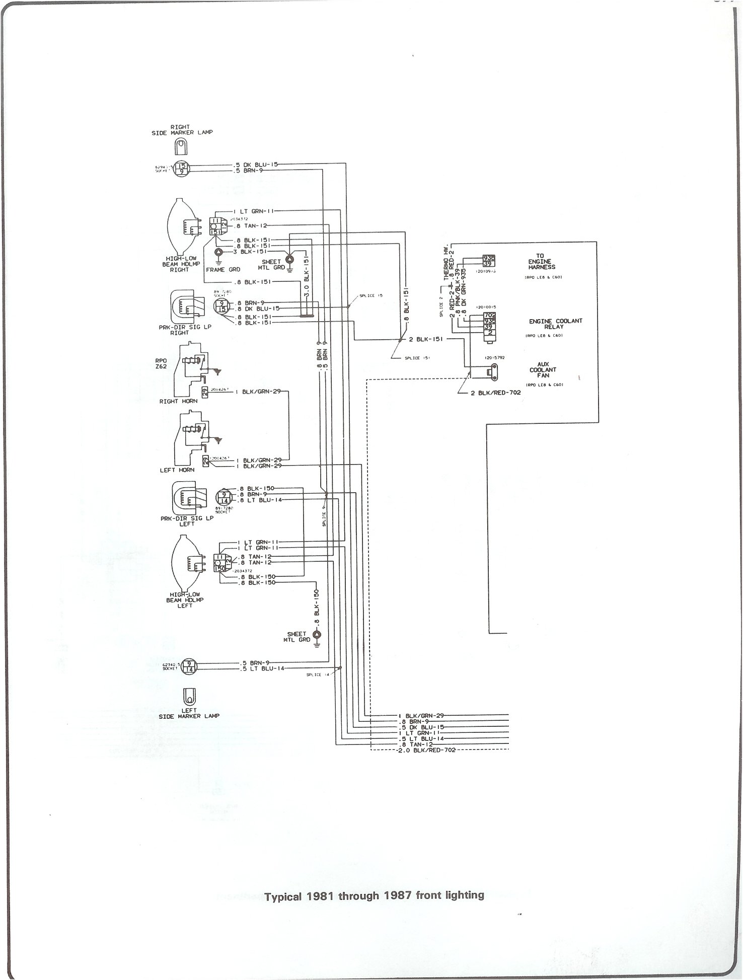
 15 81 Chevy Truck Wiring Diagram Truck Diagram Wiringg Net Chevy Trucks 1979 Chevy Truck 1984 Chevy Truck
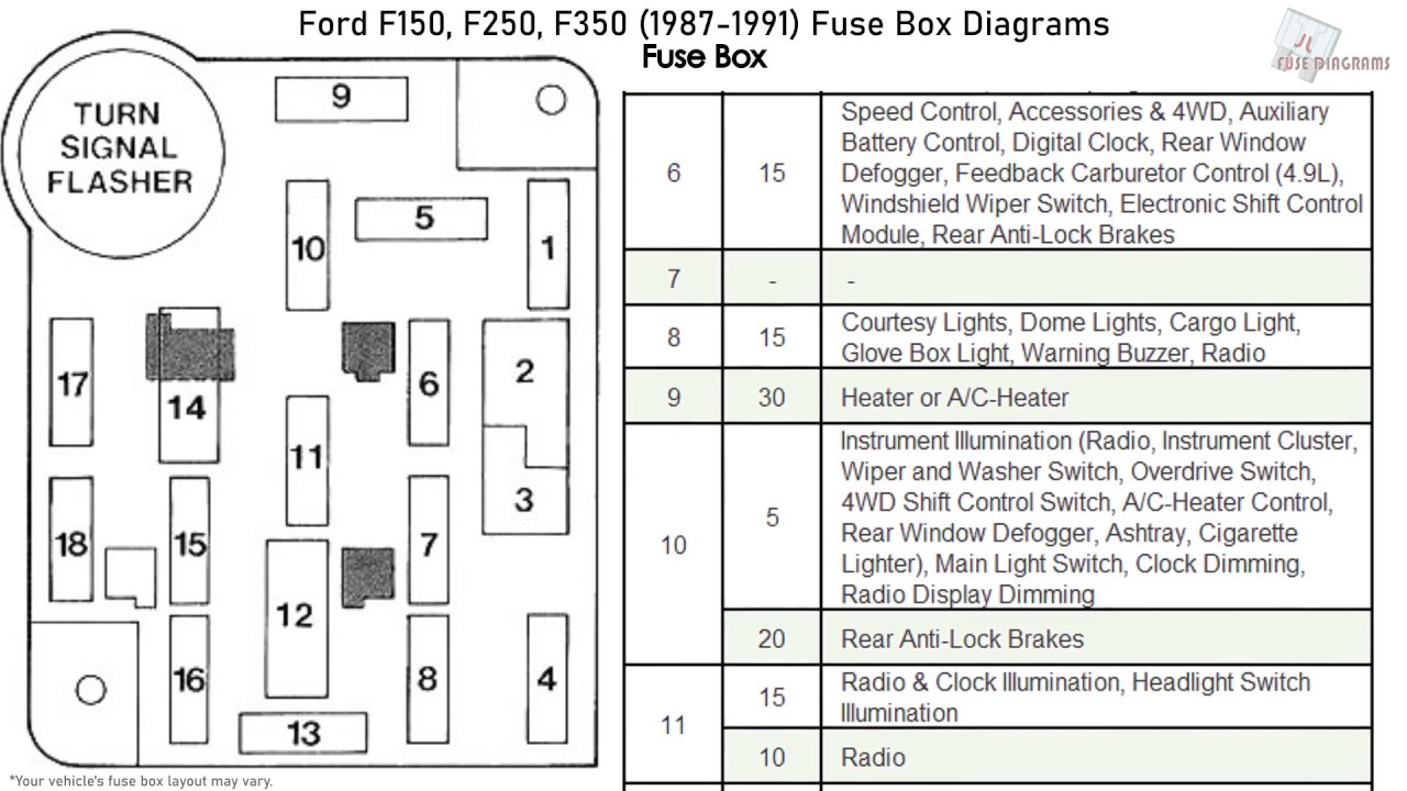 Ford F150 F250 F350 1987 1991 Fuse Box Diagrams Youtube

 Tail Light Wiring 1991 F350 Ford Truck Enthusiasts Forums
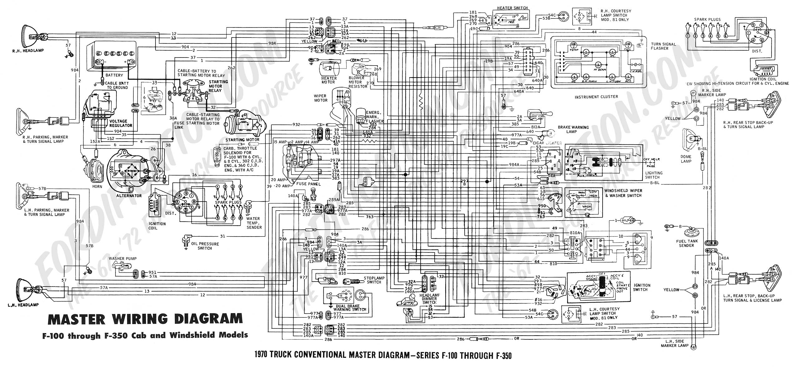 Ford Truck Technical Drawings And Schematics Section H Wiring Diagrams


